Choose the listed power and housing group to suit the required lighting level and installation envelope.
- Key data
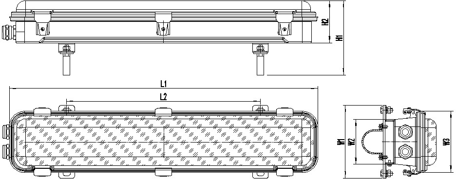
- 20 / 30 / 40 W: 685 × 162 mm · 40 / 60 W: 1305 × 162 mm
- Formats
- Confirm the ordered power, length and mounting arrangement
LED luminaires for low-canopy lighting in explosive gas or combustible-dust environments, with 304 or 316 stainless-steel construction and surface-fixed or column installation options.
Use this guide to prepare the power, mounting and emergency requirements for the selected FP07 configuration.
304 or 316 stainless-steel explosion-proof lighting for low-canopy hazardous-area installations.
Maximum temperature depends on configuration
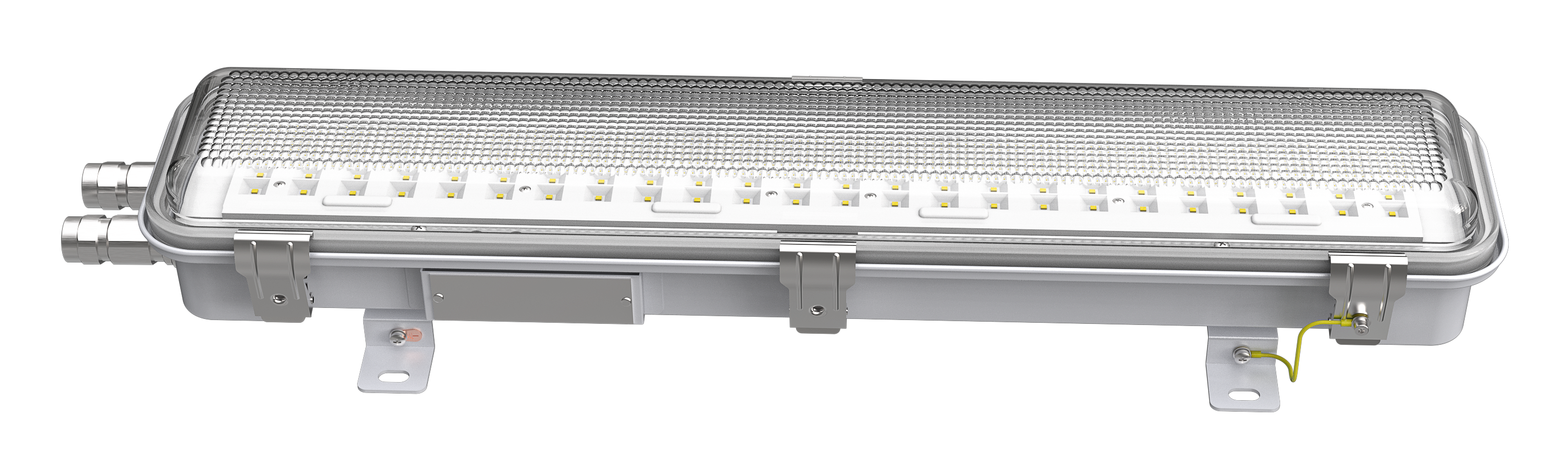
304 or 316 stainless-steel construction options, with stainless-steel buckles and a UV-resistant PC cover.
The product document lists Ex LED modules, driver power supply and optional emergency power supply within the enclosure.
IP66 protection. Select cable glands or stopping plugs with a minimum IP66 rating and suitability for the installation.
Surface-fixed installation or column installation for 40 mm, 48 mm and 60 mm pole diameters.
Hazardous-area suitability depends on the complete ordered configuration, Ex marking, cable entry and installation conditions. Confirm the project requirements before specification or installation.
Two housing lengths cover the listed power configurations. Dimensions and weights follow the current product document.
| Power group | Overall size L1 × W1 | Net weight | Packing size | Gross weight |
|---|---|---|---|---|
| 20 / 30 / 40 W | 685 × 162 mm | ≈2.6 kg | 840 × 200 × 150 mm | ≈3.0 kg |
| 40 / 60 W | 1305 × 162 mm | ≈4.5 kg | 1400 × 200 × 150 mm | ≈5.2 kg |
Temperature-class selection depends on the ordered configuration and operating conditions.
| Gas marking | Dust marking |
|---|---|
| II 2G Ex db eb mb IIC T6 Gb | II 2D Ex tb IIIC T80°C Db |
| II 2G Ex db eb mb IIC T5 Gb | II 2D Ex tb IIIC T95°C Db |
Emergency power and duration vary with the selected battery configuration.
| Battery | Voltage / capacity | Emergency power | Emergency duration |
|---|---|---|---|
| Ni-Cd | 3.6 V · 3.0 Ah | 3.5 W | ≥180 min |
| LiFePO4 | 9.6 V · 3.5 Ah | 7 W | ≥180 min |
| LiFePO4 | 9.6 V · 3.5 Ah | 10 W | ≥120 min |
| LiFePO4 | 9.6 V · 3.5 Ah | 15 W | ≥90 min |
Select any product image to inspect the full-resolution reference. Request approved outline drawings for the selected part number.
FP07 is the hazardous-area lighting path for low-canopy installations requiring a 304 or 316 stainless-steel configuration. It is distinct from RC Series, which is recessed ceiling lighting for dry vessel interiors.
| Environment | Selection focus | Recommended path |
|---|---|---|
| Low-canopy hazardous-area lighting | Gas or combustible-dust environment, selected Ex marking, voltage, power and mounting arrangement. | Review the complete ordered FP07 configuration before specification or installation. |
| Gas Zone 1 / Zone 2 or dust Zone 21 / Zone 22 | Confirm that the selected Ex marking and installation conditions correspond to the project requirement. | Use the FP07 marking options and project documentation for the exact ordered configuration. |
| Projects requiring corrosion-resistant material selection | Specify the required 304 or 316 stainless-steel material option with the project environment. | Confirm material selection, installation details and maintenance conditions during quotation. |
FP07 Series is designed for low-canopy lighting in explosive gas or combustible-dust environments, with surface-fixed or column installation options.
FP07 is available with 304 or 316 stainless-steel construction. Confirm the required material option for the project environment during quotation.
The product data lists Zone 1 and Zone 2 gas atmospheres, and Zone 21 and Zone 22 combustible-dust areas. Confirm the complete ordered Ex marking and installation conditions before use.
Listed battery emergency configurations range from 3.5 W to 15 W, with durations from 90 to 180 minutes depending on the selected battery configuration.
Confirm the ordered configuration, Ex marking, voltage, cable-entry components, mounting method and project operating conditions before installation.
Send the installation drawing, environment, quantity and documentation requirements for model confirmation.